- Home
- About Us
- Boiler Testing & Optimization
- Natural Gas Fired Boilers
- SCR Testing, AIG Tuning and Ammonia Slip (NH3) testing
- Specialized Boiler Tuning & Testing
- Pulverizer Performance & Capacity Improvements
- Pulverizer, Fan & Auxiliary Equipment Testing
- Comprehensive Boiler Inspections
- Air Emissions Testing
- Volumetric Flyash Testing
- NOx Reduction Program
- HVT Gas Sampling
- Air Flow Measurement Devices
- Comprehensive Lab & Tech Services
- Operator Training Program
- Equipment Sales
- Heat Rate Improvements
- Troubleshooting
- Boiler Slagging
- Pulverizer Fire or Explosions
- Pulverizer Vibrations Issues (Rumbling)
- Plugged Burner Lines
- Flame Instability
- Steam Temperature Control
- Reduced Unit Capacity
- Fireside Corrosion
- High Flyash LOI’s
- High Stack Opacity
- Raw Coal Spillage
- Pulverizer Performance and NOx Emissions
- Pulverizer Fineness
- SCR Catalyst Testing
- Environmental Testing
- Technical Resources
- Contact Us

SCR Testing, AIG Tuning and Ammonia Slip (NH3) testing
Innovative Combustion Technologies SCR Testing Facility
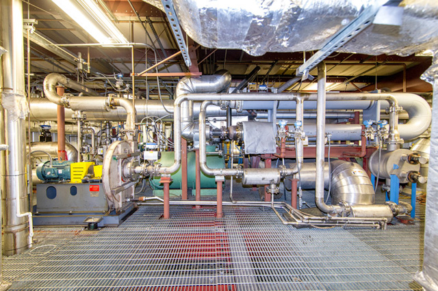
1. FURNACE
A natural gas burner is used to generate the flue gas. The air-to-fuel ratio at the burner can be adjusted to achieve the desired oxygen (O2) concentration for testing. Additionally, ammonia (NH3) is added with the air and fuel at the burner to generate nitric oxides (NOx). Pre-combustion NH3 addition is controlled to achieve the desired NOx at the testing chamber inlet.
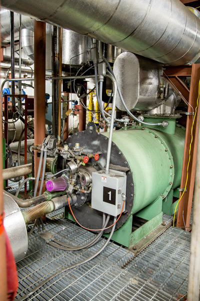
2. MOISTURE CONTROL
The facility has the capability to accurately control the moisture of the content of the flue gas to match that of full-scale operating conditions. Through the use of air-, water-, and glycol- cooled condensers, the appropriate amount of moisture is removed from the gas prior to reaching the testing chambers.
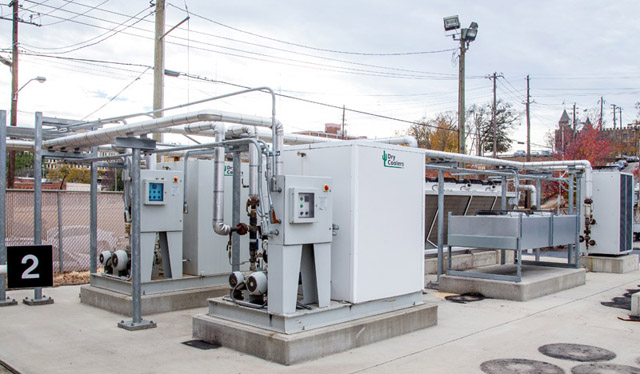
3. INJECTION POINT
At the Injection Point, the flue gas is doped with sulfur dioxide (SO2) and post-combustion NH3 at the desired levels.
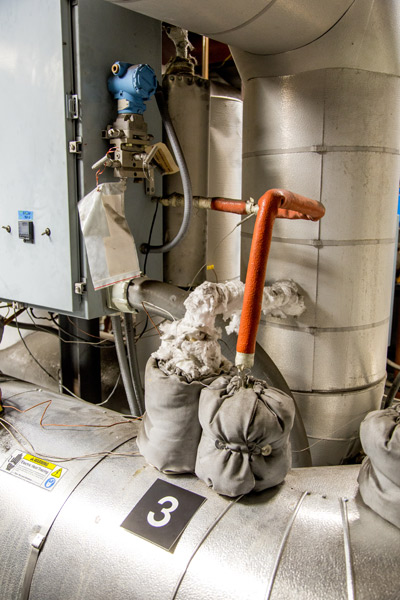
4. ELECTRIC AIR HEATER
IThe Electric Air Heater is used to re-heat the flue gas to the SCR design operating temperature after the moisture control point. The facility is capable of maintaining flue gas temperatures within the typical operating range for most SCR systems (600-800 °F).
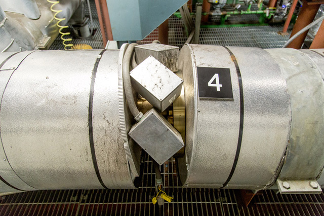
5. TESTING CHAMBERS
The Testing Chambers are equipped with heating elements to maintain the catalyst at the desired temperature. The facility is equipped with three (3) separate testing chambers.
.jpg)
5A. SO2-SO3 CONVERSION (EPA METHOD 8)
An undesired consequence of SCR catalyst is the conversion of SO2 into SO3. Controlled condensation testing is conducted at the inlet and outlet of the testing chamber simultaneously to determine the SO2-to-SO3 conversion across the catalyst sample.
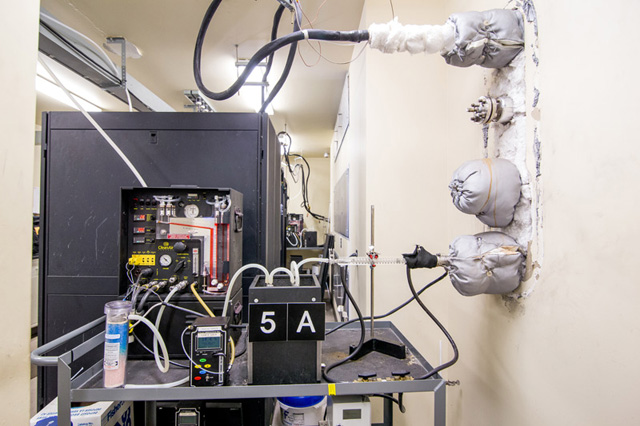
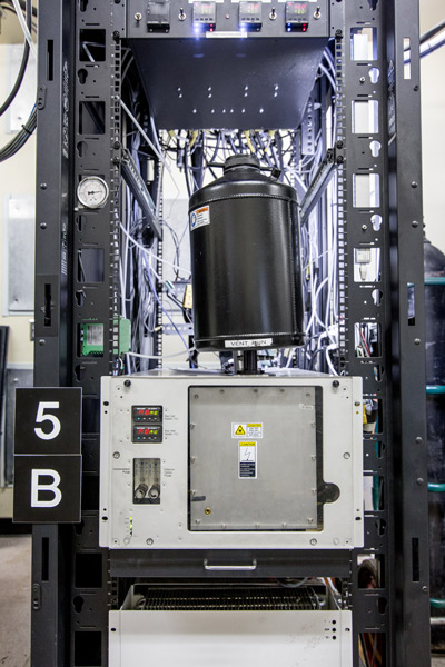
5B. DeNOX TEST
The facility is equipped with two Fourier Transform Infrared (FTIR) analyzers to measure the flue gas composition at the inlet and outlet of the testing chambers. In addition to the FTIR analyzers, a zirconia gas cell is used to measure flue gas oxygen content at the test chambers.
6. AGING CHAMBERS
aged in order to achieve stable testing results. New or regenerated catalyst samples are aged for at least 40 hours prior to testing, whereas used catalyst is aged overnight. The facility is equipped with four (4) aging chambers to increase sample throughput.
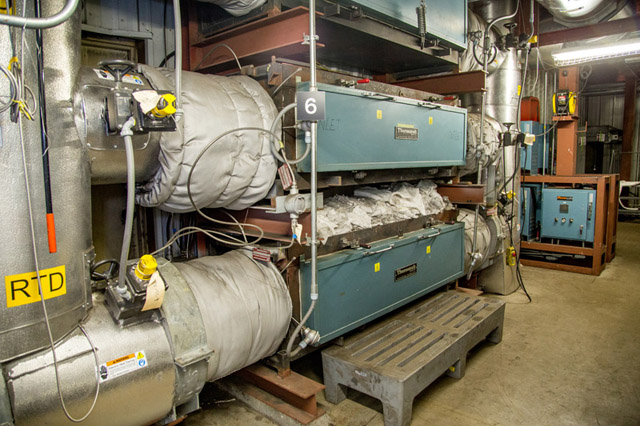
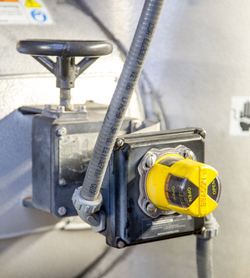
VALVE FOR TESTING AND AGING CHAMBERS
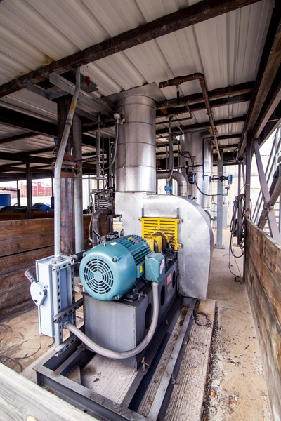
7. INDUCED DRAFT FAN
The Induced Draft (ID) Fan is used to control the gas flow through the testing chamber. Flow through the test chamber is calculated to maintain the same linear velocity through the catalyst sample as would occur during full-scale operation.
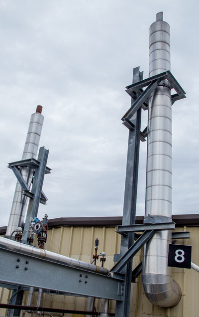
8. STACK
Flue gas exits the facility through the stack. Prior to being released to the atmosphere, heat is extracted from the gas to heat the air used for combustion.
9. FULL LAB WITH XRF ANALYSES
In addition to the bench-scale testing, chemical composition analysis by x-ray fluorescence (XRF) can be performed to determine the levels of specific catalyst poisons in each sample. Surface and bulk samples are analyzed to determine the impact of surface fouling and bulk poisoning on catalyst performance.
![]()
Boiler Slagging
Pulverizer Fire and Explosions
Pulverizer Vibration Issues
Reduced Unit Capacity
![]()
Click here for ICT's 5th Edition Quick Reference Guide
![]()
20 tips to help prevent slagging When firing
PRB Coal
Achieving Optimum Pulverizer Performance
ASME Coal Sampling Procedure
![]()
Innovative Combustion Technologies, Inc. is New Sales Agent for Loesche Energy Systems, Ltd.
EPA extends public comment period on proposed MATS reconsideration
A recent Power Magazine article highlights a presentation given by ICT President Richard Storm to the Asian SBCUG meeting in Hong Kong.
